
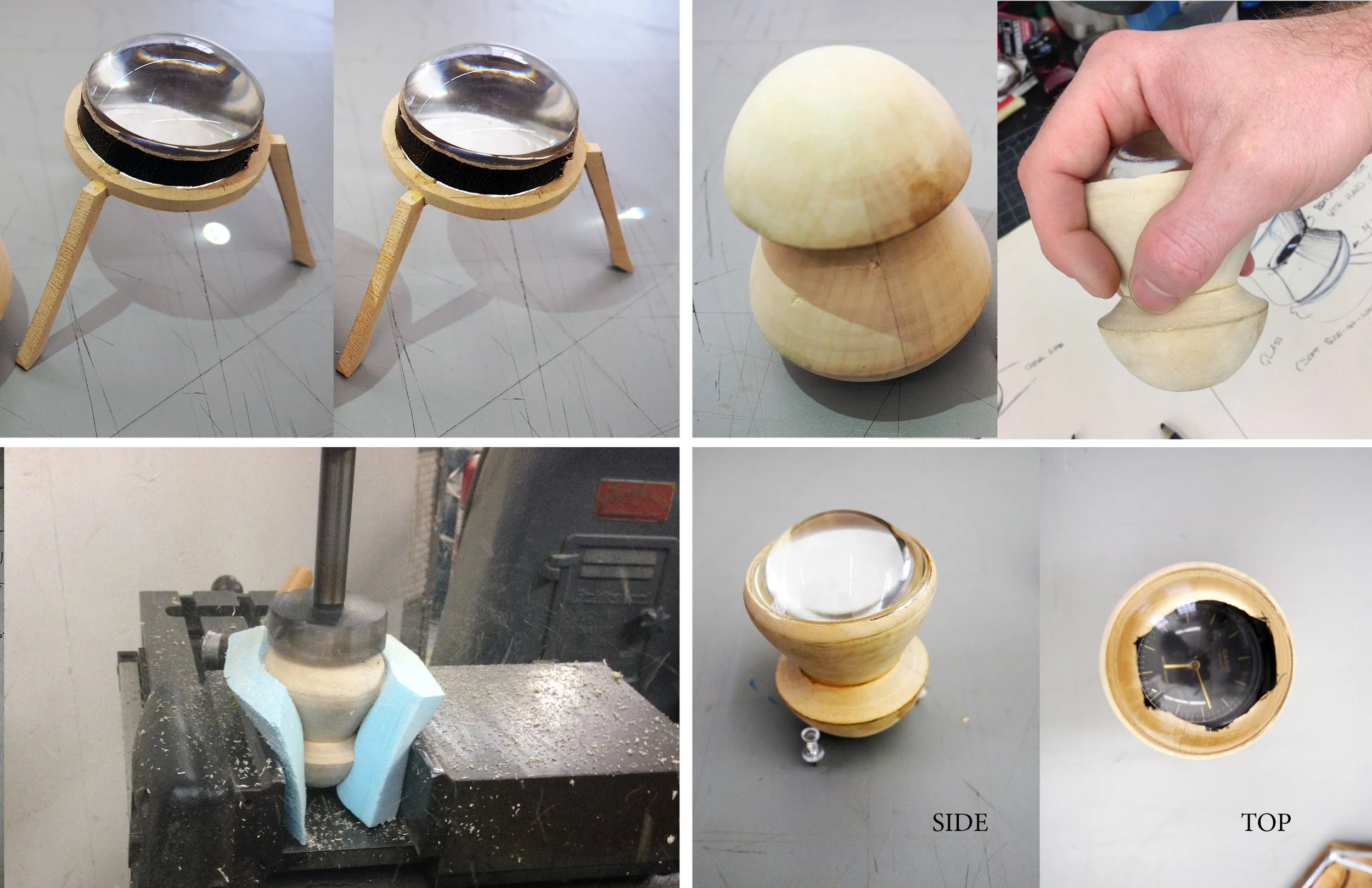
Initial Working Model of the Tip Timer.


Working "Tip Timer."
Partial Tip Timer Frame Construction Time-lapse
After more feedback, form exploration became the primary concern. Forms sketches in clay, lathed from bass wood and 3D modeled and cut by CNC.
After struggling to get just the right shape via 3D modeling, I learned to import this hand-sketched ellipse as a basis for the form.

A wood CNC sketch which was then held to a belt sander to give a hand-made look to a computer created form. A CNC sketch - blue foam and plywood - that plays with Maya's ability to create organic form.
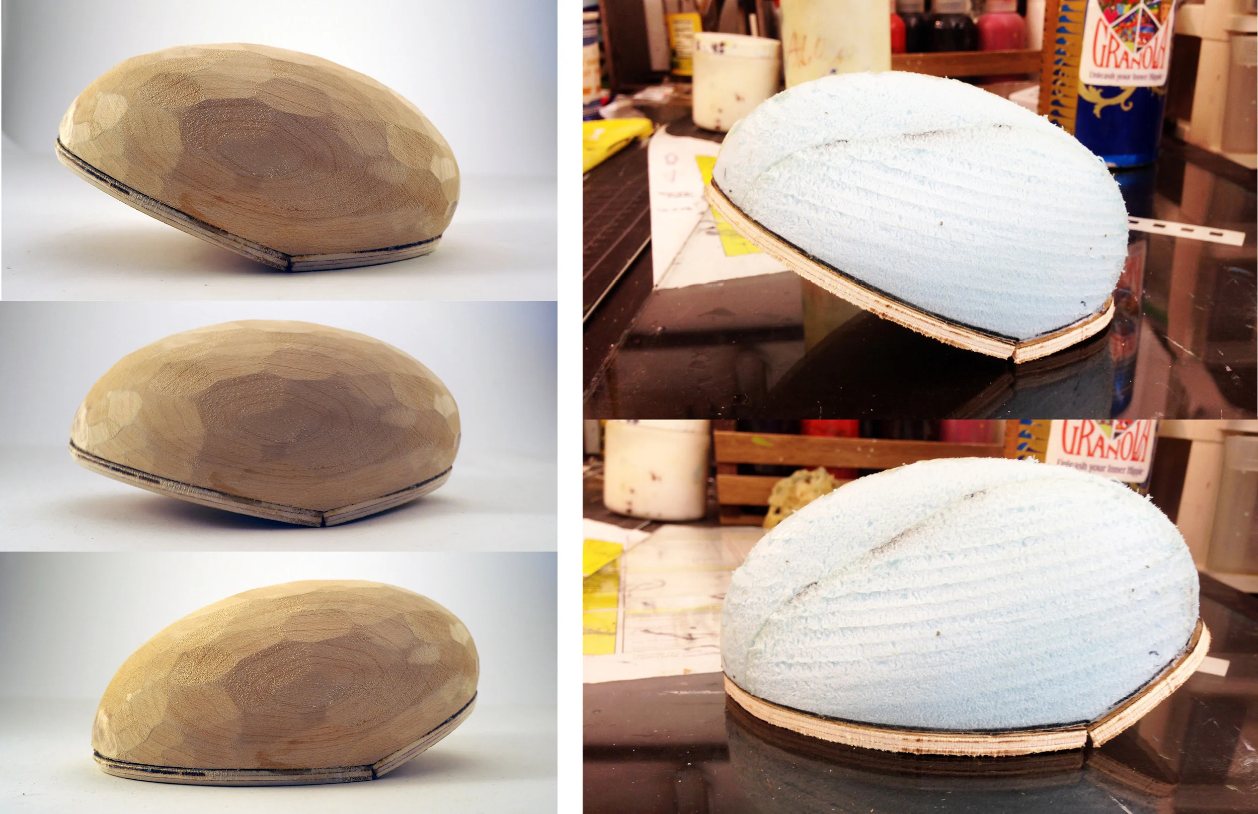
More sketches. An accidentally 3D printed form in the foreground, a lathe turned ovoid in the back, and two CNC cut pieces between.

Going down the road in the direction that the hand-held, time killing device had sent me, I started making simpler hand held play objects that would reveal time in subtle ways. This one projected light and the shadows of the hands of a clock onto a table-top The model was turned plywood, a button battery and LED, and a focusing lens pulled from the headlight of a Toyota Tundra.


In this iteration (modeled with SolidWorks and 3D printed) I sought to combine the tipping form with table-top light projection.

Enjoying the way that the light played on the inside of the 3D printed partial sphere, I began thinking of flipping the object and projecting light up into a dome. Geodesic domes hold a special place, and reminded me of the new Areaware catalog's sometimes LA aesthetic. Sketches via CNC in wood and blue foam.

At this point, practiced with the fairly complex CNC flip-job process, I applied the method to a solid block of acrylic.

Here it is mocked up and on a flat red oak base. The result was ultimately dissatisfying, and I realized that if I was going to go down this route, the dome would necessarily be made from glass.

Maya was used to model the Geodesic Dome form as well as a stellated version with sunken faces. These were then 3D printed.

These prints were cast into plaster molds into which the glass would be blow casted.


The piece in the foreground is how they came out of the mold. The others were sanded and then sandblasted.

Cutting out the interior of the turned wood base. Painstakingly painting over and over and a shot of the LED light array and the charging port placed in the bottom


Dome Clock
Bonus videos.
Jewelry student showing me how to make the brass rivet I wanted for the capacitive sensor switch.
And a side-road I may pursue in the future. The light and the shadow of the hands of the clock are projected through a lens at the top of the equilateral pyramid. I would like to eventually make this in a small flat profile. It is activated via a homemade capacitive sensor much like this.
// <![CDATA[ $('p').each(function(index){ var thisHtml = $(this).html(); console.log( index + ": " + thisHtml ); console.log(thisHtml.length); if( (thisHtml.length)>6){ $(this).addClass('two-col') } $('img, iframe').closest('p').removeClass('two-col'); }); // ]]</p></div>